Mirley - Electronics & Programming
projects, programs... all about electronics


 Currently, voltage inverters are used almost everywhere and very often replace traditional linear regulators, which for high output currents, gives a significant energy loss. Circuit described here is a simple Step-Down converter (12V to 5V) built based on the popular and inexpensive chip MC34063. The device is designed to work with 12V car installation, and can be used to charge/power GPS or mobile phones equipped with USB slot. In idle state the circuit is completely switched off and in normal operating conditions it can be automatically turn off when there are no power consumption at the output. The converter can be turn on, by a monostable switch, when load is connected to its output .
How It Works?:
At the beginning is worth to present some information about MC34063 which is monolithic controller comprising most important components needed for DC-DC converters. This device contains of: an internal temperature compensated voltage reference, comparator and oscillator with adjustable duty cycle. Moreover the MC34063 contains also a current limit circuit and high current output switch, which is able to work with currents up to 1.5A. In result to built converter only a inductor, a diode and few passive components are needed. Figure 1 shows the complete schematic of the MC34063 voltage converter.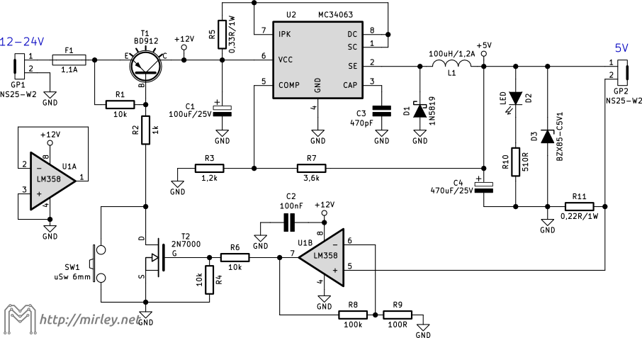
Figure 1: Schematic
Construction:
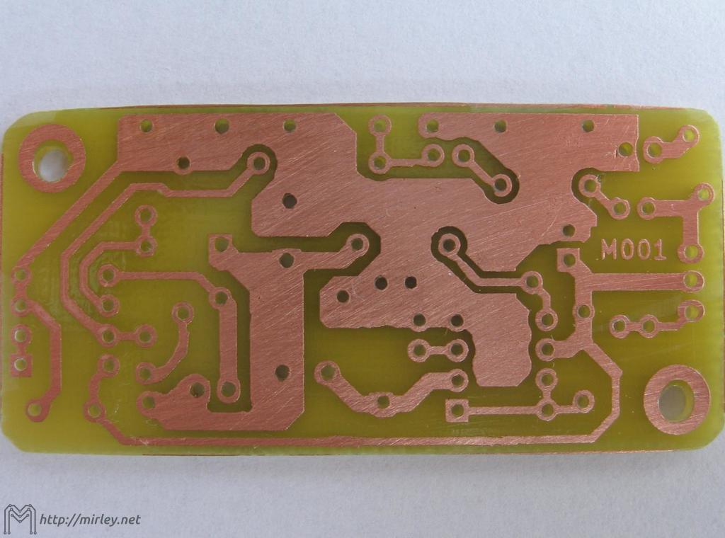
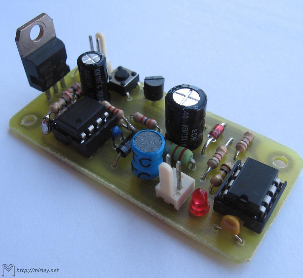
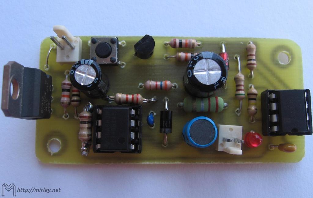
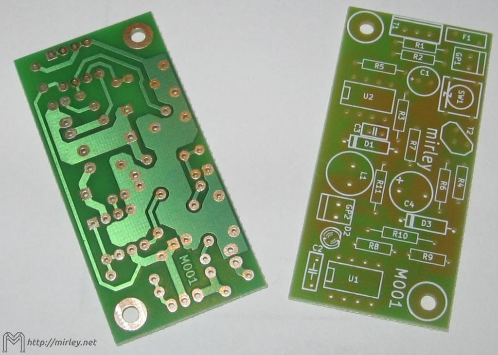
Printed circuit board (bottom side) may be downloaded here. Figure in a mirror image is available here. Helpfull for constructing the top side of printed circuit board will be schematic available here.Photos:
Parts List:
Converter's parts:
Attachments:
| PCB Design: | ||
| AB AB AB | Board (bottom side,thermotransfer method) | 21.0 kB |
| AB AB AB | Board (bottom side, mirrored) | 21.1 kB |
| AB AB AB | Board (bottom side, few per page, thermotransfer method) | 216.5 kB |
| AB AB AB | Mounting (top side) | 36.3 kB |
| AB AB AB | Description Layer (top overlay) | 156.5 kB |
| AB AB AB | Soldermask (bottom layer) | 80.6 kB |
| Documentation: | ||
| AB AB AB | Schematic | 65.9 kB |
| AB AB AB | Partlist | 1.3 kB |
| AB AB AB | Mounting List | 1.3 kB |
Questions and Comments:
comments powered by Disqus
July 19, 2018
Power supply was presented ...
More …
June 20, 2018
Triac Module was presented...
More …
More news …
Power supply was presented ...
More …
June 20, 2018
Triac Module was presented...
More …
More news …

Recommended Sites